A visually perfect packaging design holds zero value if it causes jams or registration errors on the production floor. The disconnect between digital packaging design and physical production realities often results in catastrophic manufacturing delays. Designers frequently draft layouts focusing solely on aesthetics, ignoring the mechanical constraints of the hardware that will actually cut, crease, and fold the substrate.
Poorly planned die lines lead directly to defective tooling. When die boards are cut based on flawed digital files, facilities face excessive material waste, extended makeready times, and severe machine downtime. A die board with overlapping cuts or incorrect tolerances forces operators to spend hours shimming and adjusting the press just to achieve a passable run.
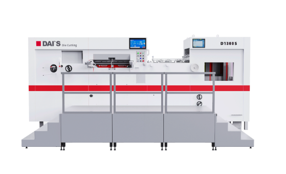
Efficient carton production requires engineering dielines specifically for the tolerances, feeding mechanisms, and output capabilities of your specific production hardware. You must bridge the gap between prepress software and the physical press. By aligning your structural files with the mechanical realities of a Carton Die Cutting Machine, you eliminate ambiguity, reduce tooling rework, and maximize production speeds.
- Machine-Specific Tolerances: A production-ready dieline must account for the specific gripper margins and registration capabilities of your equipment.
- Vector Accuracy is Non-Negotiable: Utilizing industry-standard CAD software (e.g., ArtiosCAD) prevents the overlapping lines and dimensional errors common in standard graphic design software.
- Material Dynamics Matter: Dieline planning must factor in paperboard caliper and grain direction to prevent cracking during the creasing process.
- Prototyping Prevents Failure: Physical sampling and 3D mockups are mandatory steps before commissioning expensive steel-rule dies.
- Tooling ROI: Precise prepress planning directly reduces the cost of physical die creation and minimizes makeready time on the production floor.
The Role of the Dieline in Physical Carton Production
Beyond Graphic Design
A dieline serves as much more than a digital layout for graphic placement. It operates as the exact engineering blueprint used to manufacture physical tooling. Die-makers rely on this vector data to drive CNC laser cutters, which burn precise kerfs into 18mm birch plywood die boards. The width of this laser cut must perfectly match the thickness of the steel rule—typically 2-point (0.71mm) or 3-point (1.05mm)—so the wood holds the metal tightly under immense pressure.
Automated bending machines read the exact same vector file to cut, notch, and bend the steel rules before operators hammer them into the board. Any dimensional inaccuracy in the digital file transfers directly into the physical steel. If a line is drafted 0.5mm too long, the steel rule will not fit into the laser-cut channel, rendering the entire tool useless and requiring a complete rebuild.
Hardware Synchronization
The structural integrity of the dieline dictates the operating speed and reliability of a carton die cutting and creasing machine. If a layout packs too many cartons onto a single sheet without leaving adequate structural support, the sheet will fall apart as it transfers between stations. Properly engineered dielines incorporate specific holding points—tiny gaps in the cut lines called nicks—that keep the carton attached to the waste matrix.
These nicks ensure the paperboard maintains its rigidity as it moves through the stripping and blanking sections at speeds exceeding 7,000 sheets per hour. If the dieline fails to account for the mechanical stress of the stripping pins, the waste material will explode inside the machine, causing a massive jam that takes hours to clear.
Quality Control Baseline
On the production floor, the dieline serves as the ultimate reference point. Press operators use it to evaluate box integrity, fold accuracy, and print consistency from the initial press setup to the final unit off the line. When a carton fails to fold correctly on the folder-gluer, technicians trace the issue back to the original dieline measurements.
They measure the physical blank against a printed mylar overlay of the dieline to determine if the fault lies with the tooling, the material shrinkage, or the machine setup. Without a mathematically perfect dieline, quality control teams have no baseline to measure against, turning troubleshooting into a guessing game.
Success Criteria
A successful dieline achieves zero ambiguity between prepress, the die-maker, and the machine operator. Every line, notch, and margin must communicate a specific physical action. When all parties work from a flawless structural file, makeready times plummet. Operators spend less time patching the die with shim tape or adjusting feeder timings, allowing the facility to achieve maximum throughput immediately after setup.
Pre-Planning: Product Analysis and Structural Standards
Product-First Dimensional Analysis
Before drafting a single line on a screen, you must analyze the physical product. The item's weight, dimensions, and fragility dictate the structural requirements of the dieline. A heavy glass bottle requires a reinforced crash-lock base and specific insert structures, while a lightweight cosmetic tube might only need a standard straight-tuck end.
Follow these steps for accurate dimensional analysis:
- Measure the maximum outer dimensions of the primary product using digital calipers.
- Determine the required clearance space to allow the product to slide in without tearing the paperboard.
- Calculate the internal dimensions of the carton based on the product plus the clearance.
- Build the external panels outward, adding the exact caliper (thickness) of the chosen paperboard to each fold to ensure the box closes squarely.
Leveraging Industry Standards
Designing complex custom structures from scratch introduces unnecessary risk. Utilizing established ECMA (European Carton Makers Association) standard box templates provides a reliable, machine-tested foundation. These standardized codes represent geometric layouts proven to run efficiently on industrial folder-gluers and die cutters.
By starting with an ECMA standard, you guarantee the basic folding logic is sound. This allows structural designers to focus on minor dimensional tweaks rather than reinventing the basic mechanics of a box.
Common ECMA Standards and Applications
| ECMA Code | Carton Style | Best Use Case | Production Considerations |
| A20.20 | Straight Tuck End (STE) | Cosmetics, pharmaceuticals | Folds easily on standard gluers; requires minimal board. |
| A21.20 | Reverse Tuck End (RTE) | Lightweight retail goods | Nests tightly on the sheet, maximizing material usage. |
| A60.20 | Crash-Lock Base | Heavy items, beverages | Requires specialized folder-gluer attachments for the base. |
| B01.01 | Tray with glued corners | Bakery, fast food | High-speed forming; requires precise glue flap sizing. |
3D Spatial Verification
Modern packaging requires precise spatial planning. Using 3D rendering tools verifies that all panels, tuck flaps, and dust flaps align perfectly when folded. This digital folding process eliminates spatial conflicts before physical production begins.
If a dust flap is drafted 1mm too long, it will crash into the closure panel during automated gluing, causing the carton to bulge or jam the line. 3D verification highlights these interferences instantly. Designers can rotate the virtual model, check the clearances on interlocking tabs, and adjust the vector lines accordingly, saving the cost of cutting a flawed die board.
Core Components of a Production-Ready Dieline
Standardized Line Types
Prepress departments must enforce strict color-coding and stroke requirements for different mechanical actions. A die-maker's software reads these specific colors to assign tooling. Solid red lines typically denote through-cuts, where the steel rule severs the board completely. Dashed green lines indicate creases or scores, where a blunt rule crushes the fibers to create a fold.
Specific markers, such as alternating blue dashes, dictate perforations or zipper cuts. Deviation from these standards causes the laser cutter to burn the wrong type of channel into the wood. If a crease line is accidentally colored red, the die-maker will install a cutting rule, and the machine will slice the carton into pieces instead of folding it.
Bleed and Safe Zones
High-speed mechanical systems experience micro-shifts during operation. You must extend artwork beyond the cut line to accommodate these shifts. This bleed area, usually 3mm to 5mm, ensures that slight misregistrations do not result in unprinted white edges on the final carton.
Conversely, safe zones keep critical text and logos away from creases and cut edges. Placing a barcode too close to a score line risks rendering it unreadable if the fold shifts by a fraction of a millimeter. A standard safe zone requires keeping all critical information at least 3mm away from any mechanical action line.
Glue Flaps and Assembly Logic
Automated folding and gluing lines require specific structural considerations. Glue flaps must be appropriately sized to provide enough surface area for the adhesive to bond securely. A standard side-seam glue flap should be no less than 12mm wide to accommodate the extrusion nozzles on a modern folder-gluer.
More importantly, these flaps must remain entirely free of ink, varnish, or aqueous coatings. Cold PVA adhesives and hot melt glues cannot penetrate high-gloss finishes, leading to carton failure in the field. The dieline must explicitly outline these knockout zones so the prepress team knows exactly where to pull back the artwork.
Standard Dieline Color Codes and Functions
| Line Type | Standard Color | Stroke Style | Physical Tooling Action |
| Cut Line | Red | Solid | Steel rule cuts completely through the substrate. |
| Crease / Score | Green | Dashed | Blunt rule crushes paper fibers to facilitate folding. |
| Perforation | Blue | Dotted / Dashed | Notched rule creates tear-away sections. |
| Bleed Margin | Cyan | Solid (Outer) | Defines the limit of printed artwork extension. |
| Safe Zone | Magenta | Solid (Inner) | Boundary for critical text to avoid fold distortion. |
Aligning Dieline Design with Your Carton Die Cutting Machine Specs
Sheet Size and Layout Optimization (Nesting)
Arranging multiple carton flats on a single sheet maximizes material usage and minimizes scrap. This process, known as nesting, requires interlocking the shapes like puzzle pieces. However, you must balance material efficiency with structural stability.
Designers must choose between single-knife and double-knife layouts. A single-knife layout means two cartons share a single cut line. This saves board but requires absolute perfection in printing registration. A double-knife layout leaves a 3mm to 4mm gap between cartons. While it uses slightly more material, it creates a continuous waste skeleton that strips cleanly at high speeds. Maximizing the number of cartons per sheet might leave the skeleton too thin. A weak skeleton breaks apart inside the press, causing massive jams. The dieline layout must maintain enough continuous waste material to pull the sheet safely through the stripping stations.
Gripper Margins and Feeding Mechanisms
Every sheet-fed press requires a blank leading edge for the machine's mechanical grippers to grab and pull the substrate through the cutting platen. If you place a cut line inside this gripper margin (typically 10mm to 15mm), the machine will tear the sheet and halt production.
Utilizing a leading edge feeder die cutter impacts these margin requirements. This feeding style uses vacuum belts rather than mechanical fingers, allowing for specific sheet alignment strategies compared to traditional feeding systems. It often handles warped or thicker boards more reliably. You must verify the exact minimum gripper bite required by your specific hardware and lock that margin into your digital template before nesting the cartons.
Registration Tolerances
The optical or mechanical registration systems of the machine dictate the required bleed margins and print-to-cut tolerances in the dieline file. Mechanical side-lays push the sheet into position physically, relying on the squareness of the paperboard. If your equipment relies on older mechanical registration, you must design larger bleed areas to absorb the natural variance.
Modern optical systems read printed marks to adjust the cutting platen dynamically, shifting the die board to match the print perfectly. Optical systems allow for tighter nesting and smaller bleeds, but the dieline must include precise target marks for the cameras to read. Omitting these marks from the prepress file renders the optical system useless.
Material Considerations: Designing for Paperboard
Caliper (Thickness) Adjustments
The thickness of the substrate requires specific allowances in the dieline. A layout designed for a thin 0.016" (16pt) board will fail completely if run on a thick 0.024" (24pt) board. You must adjust the dimensions of interlocking tabs, dust flaps, and double-folds to accommodate the physical space the thicker material occupies when folded.
When a carton folds, the board compresses on the inside and stretches on the outside. Failing to adjust the dieline for this caliper displacement results in bowing panels, tearing corners, and flaps that refuse to stay tucked during assembly.
Grain Direction Planning
Paperboard is composed of wood fibers aligned in a specific direction during manufacturing. A paperboard die cutting machine operates most efficiently when the main structural creases run parallel to this paper grain. Folding with the grain reduces resistance and creates a clean, sharp edge.
Folding against the grain forces the fibers to snap, resulting in ugly, cracked creases that ruin the printed artwork and weaken the box. The dieline layout must dictate the grain direction on the master sheet. Prepress teams indicate this by drawing an arrow on the layout file, ensuring the printing department cuts the raw material to align the primary folds correctly.
Creasing Rule Specifications
Dieline data informs the die-maker on which point-size creasing rules to install. The selected paperboard grade and caliper dictate the geometry of the crease. A thick board requires a wider creasing rule and a corresponding wider channel in the counter-matrix (the phenolic plate beneath the sheet).
Die-makers use a strict formula to determine the matrix channel width: (Paperboard Caliper x 1.5) + Creasing Rule Thickness. The structural designer must communicate the exact material specs alongside the dieline so the tooling manufacturer can calculate this formula correctly. If the channel is too narrow, the board will burst; if it is too wide, the fold will be sloppy and undefined.
Common Dieline Errors That Cause Machine Downtime (Implementation Risks)
Overlapping or Duplicate Vector Paths
Hidden duplicate lines represent one of the most destructive prepress errors. If a designer accidentally copies and pastes a cut line directly on top of itself, the vector file looks identical on screen. However, the laser cutter will read both lines and cut the die board twice in the exact same spot.
This double-burn widens the kerf, resulting in loose steel rules that fall out during high-speed production. A loose rule flying through the cutting platen causes catastrophic machine failure, destroying the counter-plates and requiring massive repairs.
Prepress Handoff and File Format Failures
Exporting dielines in flattened formats or non-CAD files introduces massive risk. Standard graphic design software often alters vector paths during export, changing precise curves into jagged line segments. Sending a flattened PDF to a die-maker destroys the layered data they need to separate cuts from creases.
You must use dedicated formats like layered PDFs, DXF, or CF2 to ensure the die-maker receives uncorrupted, dimensionally stable vector data. These formats preserve the exact mathematical coordinates of every line, ensuring the laser cuts exactly what the designer intended.
Inadequate Bleed on Complex Shapes
Complex geometric cartons often feature tight angles where designers struggle to extend the artwork properly. Inadequate bleed on these complex shapes causes severe production delays. When operators notice white edges appearing on the cut blanks, they have to slow down the machine significantly to compensate for tight print-to-cut margins, killing the shift's productivity.
Ignoring Machine Maximums/Minimums
Designing a layout that exceeds the maximum cutting area of the hardware results in immediate rejection by the production floor. Similarly, falling below the minimum sheet size specifications means the feeder cannot physically transport the board. You must hard-code the mechanical limits of your specific press into your CAD software to prevent designers from creating unmanufacturable layouts.
Mitigation Strategy
Implement mandatory prepress pre-flight checklists to catch errors before they reach the die-maker.
- Run a vector cleanup tool to delete all duplicate or overlapping paths.
- Verify that all bleed margins extend a minimum of 3mm past the cut lines.
- Confirm the gripper margin is completely free of artwork and cut lines.
- Check that all glue flaps are designated as ink-free knockout zones.
- Cut a blank sample using a digital plotter table to verify dimensions, fold logic, and flap clearances before commissioning the expensive steel-rule die.
Evaluating the ROI of Standardized Prepress Workflows
Feature-to-Outcome
Connecting the use of dedicated packaging CAD software to actual production outcomes reveals massive ROI. Software built specifically for packaging automatically calculates caliper allowances and prevents duplicate lines. This directly reduces tooling rework.
When the die board arrives perfectly matched to the printed sheet, makeready times drop from hours to minutes. Operators do not have to spend time shimming a poorly made die with tape to force it to cut evenly. The press starts producing sellable cartons faster, increasing the overall capacity of the plant.
Scalability
Maintaining a library of standardized, machine-tested dieline templates accelerates time-to-market for new product SKUs. When a client requests a new carton size, structural designers do not start from scratch. They pull a verified template, input the new dimensions, and the software scales the entire structure while maintaining the correct flap ratios and machine tolerances. This scalable workflow handles high-volume demands effortlessly and eliminates the risk of human error during drafting.
Overall Value Influencing Factors
Weigh the upfront cost of premium prepress software and operator training against the long-term savings. The initial investment pays for itself by reducing material waste, eliminating the cost of ordering replacement dies, and maximizing machine uptime. A press that runs continuously at 7,000 sheets per hour because the tooling is perfect generates far more revenue than a press constantly stopped for manual adjustments.
Conclusion
Efficient carton production remains impossible without a dieline engineered specifically for the physical realities of the die cutting hardware and the chosen substrate. Digital aesthetics mean nothing if the physical sheet cannot survive the mechanical journey through the press. Precision in the prepress stage dictates the profitability of the entire production run.
Businesses experiencing high waste, tooling failures, or slow run speeds should audit their prepress dieline protocols immediately. Do not assume the fault lies with the machine or the operator. More often than not, the root cause is a structurally flawed vector file that forces the hardware to operate outside its optimal parameters.
Take the following steps to optimize your production:
- Audit your current prepress software stack to confirm you use true CAD programs rather than generic illustration tools.
- Map out exact machine-specific tolerances, gripper margins, and rule heights with your die-maker.
- Mandate a physical prototyping phase using a plotter table before ordering any steel tooling.
- Standardize your internal file handoff formats to DXF or CF2 to prevent vector corruption.
FAQ
Q: What software is best for creating carton dielines?
A: Vector-based CAD software like ArtiosCAD is the industry standard for packaging. Unlike standard graphic design tools, CAD software ensures exact dimensional accuracy, automatically calculates material thickness allowances, and exports clean DXF or CF2 files required by die-makers for laser cutting.
Q: How much bleed is required for a carton die cutting machine?
A: Industry standards typically require 1/8 inch or 3mm of bleed extending past the cut line. This accommodates minor mechanical shifts during high-speed runs. However, older machines with mechanical registration may require up to 5mm of bleed to account for larger variances.
Q: What is the difference between a cut line and a score line in prepress?
A: A cut line dictates where a sharp steel rule severs the paperboard completely. A score line dictates where a blunt rule crushes the fibers to create a fold. In prepress vector files, these must be distinctly color-coded so the tooling software assigns the correct action.
Q: How does a leading edge feeder impact dieline planning?
A: A leading edge feeder pulls the sheet using vacuum belts at the front edge, which changes the required gripper margin compared to traditional mechanical grippers. Dieline planners must adjust the layout's leading edge blank space to match the specific bite requirements of this feeding mechanism.
Q: Why do paperboard grain directions matter in dieline design?
A: Paperboard fibers align in one direction. Creases running parallel to the grain fold cleanly and easily. Creases running perpendicular to the grain resist folding and often crack, ruining the ink. Dielines must be oriented so the primary structural folds align with the paper grain.
Q: Can graphic design software replace CAD for packaging?
A: No. While graphic software is necessary for applying artwork, it lacks the engineering tools required for structural design. It cannot automatically adjust for material caliper, verify 3D spatial conflicts, or generate the specific tooling paths die-makers need without manual, error-prone adjustments.


