Web tension instability operates as a hidden cost in continuous conversion manufacturing. It directly causes matrix breaks, registration drift, and compromised yield on the shop floor. Modern converters often prioritize speed and large-volume output to meet tight production schedules. However, improper tension management leads to severe material deformation during the cut. Substrates shrink or stretch unpredictably under load, resulting in out-of-tolerance parts and excessive scrap rates that eat into profit margins. Evaluating the web handling and tension control architecture of a Rotary Die Cutting Machine remains the most critical step for ensuring production viability. This evaluation proves especially necessary for complex, high-speed, or multilayer material runs where precision dictates operational success. Operators cannot simply outrun poor web handling mechanics.
Key Takeaways
- Material Dynamics: Web materials under tension will elongate in the machine direction and shrink in the cross direction, requiring precise tooling compensation and tension isolation to maintain accuracy.
- Equipment Architecture: High-performance converting requires closed-loop tension control, utilizing load cells and servo-driven draw rolls to isolate the die station from unwind/rewind fluctuations.
- Defect Mitigation: Uneven pressure and tension spikes are the root causes of edge defects, incomplete cuts, and premature tooling wear.
- Purchasing Criteria: When evaluating an automatic rotary die cutter, the sophistication of its web handling system is a more accurate predictor of ROI and waste minimization than maximum operating speed alone.
The Physics of Web Tension in Rotary Die Cutting
Material Deformation: Shrinkage and Elongation Dynamics
Substrates running through a continuous conversion process obey strict physical laws. When pulling force applies to a web, the material undergoes strain. According to Poisson’s ratio, as the web elongates in the machine direction (MD), it simultaneously narrows in the cross direction (CD). This dimensional shift happens before the material even enters the cutting station. Once the die severs the substrate and the part exits the tension zone, the material relaxes. The cut-out part will naturally shrink in length and grow in width as it returns to its resting state.
Tooling engineers must calculate this tension-induced distortion before manufacturing the die. They engineer accurate die cylinder circumferences based on predictable web stretch. Adjusting blade spacing and pitch compensates for these dimensional changes.
Here are the standard steps tooling engineers take to compensate for material deformation:
- Measure the exact caliper and tensile strength of the raw substrate.
- Run a blank web through the press at production speed to record the baseline tension profile.
- Calculate the expected machine direction elongation percentage.
- Adjust the die blade pitch on the CAD file to cut slightly longer than the final target dimension.
- Machine the rotary cylinder to match the compensated CAD geometry.
If the tension profile during production deviates from the tension profile used during the tooling calculation, the final parts will fail quality inspection. Consistent tension ensures the physical deformation remains constant, allowing the tooling compensation to work effectively.
The Impact on Registration and Cut Tolerances
Tension variations cause the web to drift out of phase with the cutting cylinder. Maintaining tight tolerances relies entirely on a simple rule: consistent tension equals consistent registration. When tension drops, the web lags, causing the cut to shift forward relative to the printed graphic. When tension spikes, the web stretches further, shifting the cut backward.
Errors compound rapidly in multi-station setups. If a machine features multiple die stations, print stations, or laminating nips, tension must remain isolated between each process. Failing to isolate these zones means a tension spike at the unwind will ripple through the entire machine. Operators will chase registration targets endlessly, generating massive amounts of waste. True precision requires locking the web into a stable state at every conversion point.
Tension Variation vs. Registration Drift
| Tension State | Web Behavior | Registration Impact |
| Optimal (Baseline) | Stable elongation | Dead center cut |
| +10% Tension Spike | Over-stretching | Cut shifts backward (short part) |
| -10% Tension Drop | Under-stretching / Slack | Cut shifts forward (long part) |
| Fluctuating | Pulsing | Random wandering and edge defects |
Key Web Tension Factors Affecting a Rotary Die Cutting Machine
Unwind and Rewind Tension Zones
A standard converting line divides into distinct tension zones. The unwind zone relies on braking systems to hold back the material. The internal process zone uses nipping to stabilize the web through the cutting station. The rewind zone depends on clutches or independent drives to pull the finished matrix and product. Massive roll diameter changes occur at the unwind and rewind stations during large-volume production runs. A full unwind roll requires significant brake torque to maintain tension. As the roll depletes, the required torque drops.
These diameter changes create extreme tension variations if not actively managed. Without automatic compensation, the web will stretch excessively at the beginning of a roll and go slack near the core. This fluctuation risks roll telescoping, where the rewound material pushes out laterally like a telescope. Active tension management tapers the pulling force to build a stable, flat-edged finished roll. Operators running a rotary die cutting and creasing machine must monitor these zones closely to prevent substrate cracking.
Nipping and Draw Roll Synchronization
Nip rollers isolate the die-cutting station from upstream and downstream tension disturbances. A driven elastomer roll presses against a steel idler, clamping the web securely. This clamping action prevents tension spikes from the unwind or rewind from reaching the delicate cutting process. The nip establishes a controlled tension island.
Precise speed synchronization between the draw rolls and the die cylinder prevents web snapping or slack. If the draw roll pulls slightly faster than the die cylinder rotates, tension builds inside the process zone until the web breaks. If the draw roll runs slower, the web loses tension, wanders laterally, and loses registration. Advanced systems use electronic gearing to lock the nip roll speed perfectly to the die cylinder rotation.
Primary factors for effective nipping include:
- Durometer of the rubber roller matching the substrate thickness.
- Adequate pneumatic pressure applied evenly across the web width.
- Clean, debris-free roller surfaces to prevent micro-slipping.
- Proper wrap angle around the nip to maximize surface contact.
Tooling Pressure vs. Web Tension
Vertical cutting pressure and horizontal web tension interact constantly during operation. Uniform pressure across the web width maintains tight tolerances and reduces edge defects. This balance is required for multilayer materials where different layers require different cutting forces. Operators often confuse tension problems with pressure problems on the shop floor.
Excessive web tension can mask underlying bearer or leveling issues. If the die fails to cut cleanly on one side, an operator might increase web tension to pull the matrix harder. This forces a clean break but accelerates anvil wear and damages the die blades. It complicates the troubleshooting process by hiding mechanical faults behind aggressive web handling. Proper procedure dictates setting the tension to the material specification first, then adjusting the cutting pressure.
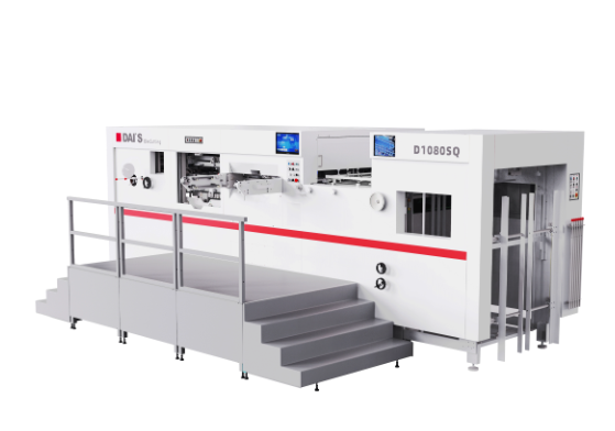
Evaluating Tension Control in an Automatic Rotary Die Cutter
Closed-Loop vs. Open-Loop Tension Systems
Open-loop systems rely on manual adjustments or diameter-calculated braking. They assume the tension is correct based on math but lack real-time feedback to verify it. If material thickness varies or a brake pad glazes over, an open-loop system cannot correct the error. Closed-loop systems continuously monitor the web using sensors and adjust the torque instantly based on actual conditions.
This technological difference drives operational outcomes. Closed-loop systems drastically reduce setup waste and operator intervention. The machine automatically finds and holds the correct tension target. This capability directly improves the machine's overall return on investment by maximizing uptime and minimizing scrap.
Tension Control System Comparison
| Feature | Open-Loop Systems | Closed-Loop Systems |
| Feedback Mechanism | None (Relies on diameter calculation) | Real-time (Load cells or dancer rolls) |
| Operator Intervention | High (Requires manual tweaking) | Low (Automatic compensation) |
| Registration Accuracy | Moderate to Poor | Exceptional |
| Waste Generation | High during roll changes | Minimal |
| Ideal Application | Simple, single-layer materials | Complex, multilayer, high-speed runs |
Load Cell and Dancer Roll Configurations
Engineers utilize two primary methods for measuring and managing web tension. Load cells measure actual web force by detecting minute deflections in a specialized idler roll shaft. They provide highly accurate, instantaneous tension readings directly to the controller. Dancer assemblies use a pivoting roll loaded with air pressure to absorb sudden tension transients. As tension changes, the dancer arm moves, and a sensor reads its position to adjust the drive.
The ideal configuration for high-speed, precision converting operations often involves a hybrid approach or highly responsive load cells. Load cells excel at maintaining exact tension profiles for registration-critical work. Dancer rolls excel at absorbing mechanical shocks during rapid acceleration or splice passes. Selecting the right configuration ensures continuous tension profiling without snapping delicate webs.
Servo-Driven Web Handling Capabilities
Legacy machines rely on a single main motor driving multiple stations via line shafts and gearboxes. Modern equipment utilizes independent servo motors for each tension zone. A servo-driven automatic rotary die cutter delivers unmatched precision. The controller commands each motor independently, allowing for microscopic tension adjustments on the fly.
These machines handle rapid acceleration and deceleration without losing registration. The servo drives communicate in milliseconds, ensuring the unwind, nip, die station, and rewind all ramp up in perfect synchronization. This eliminates the waste typically generated while bringing a mechanical machine up to production speed.
Calibration and Maintenance of Tension Components
Even the most advanced tension control system fails if the mechanical components degrade. Worn nip rollers lose their grip, allowing the web to slip and destroying tension isolation. Degraded brake pads cause pulsing or grabbing at the unwind, sending shockwaves through the material. Uncalibrated load cells report false data to the controller, causing the system to apply incorrect torque.
Facilities must establish a strict preventative maintenance schedule:
- Verify load cell calibration monthly using certified weights.
- Inspect nip rollers for uneven wear and perform durometer checks quarterly.
- Clean brake pads and rotors to remove dust buildup that causes grabbing.
- Check dancer arm pneumatics for air leaks or sticking cylinders.
- Confirm servo motor encoder feedback loops are free of electrical noise.
This maintenance ensures the web handling system continues to deliver peak performance over its operational lifespan.
Material-Specific Tension Challenges and Machine Requirements
Extensible Films and Synthetics
Converting highly extensible materials like polyethylene (PE), biaxially oriented polypropylene (BOPP), or unsupported films carries high risk. These substrates stretch significantly under minimal force. If the machine pulls too hard, the film deforms permanently. The printed graphics distort, and the cut parts fail dimensional inspection.
Operators need ultra-low tension capabilities to process these materials successfully. The machine must utilize specialized low-friction idler bearings and highly sensitive load cells. Specialized nip coatings prevent slipping without requiring massive clamping force. The entire web path must minimize drag to prevent unwanted stretching during the feed cycle.
Paper, Board, and Multilayer Laminates
Rigid and semi-rigid substrates demand higher pulling forces to move through the machine smoothly. Heavy materials resist bending around idler rolls, requiring higher torque from the drives.
However, too much tension can crack the board at the crease lines before it reaches the delivery section. Multilayer laminates present another challenge. If tension is uneven across the layers during lamination, the final product will curl. The machine must independently control the tension of each layer before they join at the nip.
Adhesives and Liners
Kiss-cutting down to a release liner requires a precise tension differential. The face stock must cut cleanly while the silicone liner remains untouched. Improper tension causes the waste matrix to break during stripping. If the rewind pulls the matrix too hard, it can lift the die-cut parts off the liner.
Furthermore, improper tension balance between the face stock and the liner during the initial lamination causes the liner to curl severely post-conversion. The machine must maintain flat web dynamics through the cutting station to ensure the die blade penetrates exactly to the silicone layer and no further.
Troubleshooting Tension-Related Defects in an Automatic Die Cutting Machine
Diagnosing Matrix Breaks and Incomplete Cuts
Matrix stripping failures halt production instantly. Operators must differentiate between excessive rewind tension, poor stripping angles, and poor die strike. If the matrix snaps cleanly across the web, excessive rewind tension or a blunt stripping angle usually causes the fault. Adjusting the matrix rewind torque or repositioning the stripping bar solves this issue.
If the matrix breaks jaggedly or pulls the part with it, poor die strike is likely to blame. Too little tension causes the web to wander laterally. This wandering results in incomplete cuts on the edges of the web as the material drifts outside the die blade path. Increasing nip pressure and verifying edge guide sensors corrects lateral drift.
Matrix Troubleshooting Guide
| Symptom | Likely Cause | Corrective Action |
| Clean snap across web | Rewind tension too high | Reduce rewind torque taper |
| Jagged tear at part edge | Dull die blade or low pressure | Increase anvil pressure or retool |
| Matrix lifting parts off liner | Stripping angle too shallow | Move stripping bar closer to nip |
| Web wandering laterally | Insufficient process tension | Increase nip clamping force |
Correcting Anvil and Cylinder Deflection
Uneven tension across the web width often points to severe mechanical faults rather than simple web handling failures. Tramming issues, bearer wear, or cylinder deflection cause one side of the web to pull tighter than the other. Web handling adjustments cannot fix broken hardware. Operators will notice the material bagging on one side of the machine.
Mitigation requires mechanical intervention. Technicians must utilize adjustable clearance anvils to compensate for bearer wear. Installing hydraulic pressure bridges ensures uniform pressure across the entire cylinder width, preventing deflection in the center of the die. Once the mechanical baseline is restored, tension control systems function correctly.
Mitigating Speed-Induced Tension Spikes
Running an automatic die cutting machine at maximum speed without proper tension profiling invites disaster. Sudden speed changes shock the web. The inertia of heavy unwind rolls resists rapid acceleration, causing the web to stretch or snap.
Facilities must implement strict acceleration and deceleration ramping protocols. The machine PLC should dictate a smooth speed curve, allowing the tension controllers time to adjust torque outputs. This ramping prevents web breaks during splice transitions and high-speed continuous runs, protecting both the material and the tooling.
Conclusion
To optimize your converting line and eliminate tension-related defects, implement the following steps immediately:
- Audit your current waste logs to identify specific shifts or materials experiencing high rates of registration drift and matrix breaks.
- Schedule a preventative maintenance check on all nip rollers, load cells, and brake pads to ensure baseline mechanical stability.
- Run a material trial with your equipment manufacturer to validate closed-loop tension control capabilities on your most difficult extensible films.
- Upgrade legacy open-loop braking systems to servo-driven, closed-loop tension zones to isolate the cutting station from unwind fluctuations.
FAQ
Q: What is the ideal web tension for rotary die cutting?
A: Ideal web tension varies based on material thickness, elasticity, and width. It is measured in PLI (Pounds per Linear Inch). Extensible films require very low PLI (e.g., 0.25 - 0.5 PLI) to prevent stretching, while rigid paperboards demand higher PLI (e.g., 2.0 - 4.0 PLI) to maintain stability. There is no single universal number.
Q: How does web tension affect kiss cutting?
A: Web tension directly impacts liner stability. If tension fluctuates, the material thickness passing under the blade varies microscopically. Consistent tension keeps the web flat and taut, preventing the die blade from cutting through the silicone release layer and ensuring the waste matrix strips cleanly.
Q: Why does my cut part shrink after rotary die cutting?
A: Materials elongate in the machine direction when placed under tension. Once the die cuts the part and the material exits the tension zone, it naturally relaxes and shrinks back to its original state. Die makers must calculate this elongation and adjust the tooling dimensions to compensate.
Q: What is the difference between a load cell and a dancer roll?
A: A load cell is a rigid sensor that measures actual web tension force precisely without moving. A dancer roll is a pivoting mechanical arm that moves to absorb sudden tension spikes and slack, using its position to signal drive adjustments. Load cells offer precision; dancers offer shock absorption.
Q: Can tension control fix uneven die cutting pressure?
A: No. Tension control cannot fix mechanical tooling issues like bearer wear, leveling problems, or cylinder deflection. While proper tension prevents lateral web wander, operators must correct uneven cutting pressure using adjustable anvils, hydraulic bridges, or tooling replacement.
Q: How do you prevent matrix breaks at high speeds?
A: Preventing matrix breaks requires independent matrix rewind tension control, optimized stripping angles, and consistent process zone tension. The rewind must taper its pulling force as the waste roll grows. Keeping the stripping bar close to the die nip also reduces the force required to separate the matrix.


